The core requirements of inductive/impact loads (such as motors, compressors, fans, pumps and transformers) for power frequency online UPS focus on five aspects: impact resistance, strong overload, pure waveform, reliable isolation and sensitive protection. The following are specific parameters and design requirements that can be grounded.
I. Topology and structure requirements (must be online at power frequency)
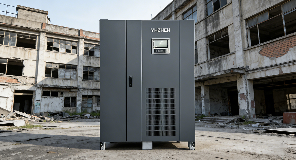
Double transformation on-line type (power frequency machine)
Built-in power frequency output isolation transformer (50Hz) can buffer the back electromotive force when inductive load starts and stops, isolate shocks and surges, and protect the inverter.
Zero switching time (< 5ms) to avoid tripping caused by voltage drop during impact.
It is forbidden to use high-frequency machines, standby machines and online interactive machines: semiconductors are weak in impact resistance and easy to explode.
Power factor matching
Example: 10kW motor (PF=0.8)→ rated 12.5kVA → choose 37.5~62.5kVA power frequency UPS.
The output power factor of UPS is ≥0.8 (preferably 0.9 ~ 1.0), and the adaptive inductive load is low PF (0.5 ~ 0.8).
The rated capacity needs to be enlarged by 2 ~ 5 times: the starting current of the motor is 3 ~ 7 times rated, and the kVA is converted according to the impulse current.
Second, the output performance parameters (impact core)
1. Overload capacity (key indicator)
110%: continuous operation (long-term load fluctuation).
125%: ≥ 10 minutes (to deal with short-term overload).
150%: ≥ 1 minute (bearing motor starting impact).
200%: ≥ 200 ms (transient spike tolerance).
2. Current peak coefficient (crest factor CF)
≥3:1 (required), preferably ≥5:1, matching 3 ~ 7 times the peak current of the motor.
Formula: UPS capacity = load kVA× (load CF/UPS CF).
3. Waveform quality
Pure sine wave, THDV < 3% (linear load), < 5% (nonlinear/inductive load).
Avoid square wave/quasi-square wave: it will lead to motor heating, loud noise and insulation aging.
4. Voltage and frequency stability
Static voltage accuracy: 1% (220v/380v).
Transient fluctuation: ≤ 5%, recovery time < <10ms (no pressure loss during startup).
Frequency stability: 0.2% (battery mode), ensuring the stability of motor speed.
Third, the inverter and transformer design (impact-resistant foundation)
Power frequency output transformer
Iron core: high-quality silicon steel sheet, which is saturated and impact-resistant, and can withstand 6 ~ 8 times instantaneous impact current.
Winding: thick copper wire, low internal resistance, low heat loss, restraining surge and reverse voltage.
Inverter power device
The current margin of IGBT/thyristor is ≥3 times, so as to prevent impact, overcurrent and burning.
Full digital DSP control, fast current loop response (≤1ms), and suppression of impact peak.
Buffer and absorption circuit
Standard surge suppressor (SPD), RC absorption loop and varistor absorb the back electromotive force (peak can reach 1000V+) when the inductive load is disconnected.
Fourth, the protection function (no misoperation, no refusal to move)
Overcurrent/short circuit protection
Inverse time characteristics: short-term big impact does not trip, continuous overload and reliable action.
Short-circuit protection: ≤200μs fast turn-off to avoid device damage.
Overvoltage/undervoltage protection
Short-term fluctuation of * * 10% * * is allowed during startup to avoid misoperation protection.
Load identification and impact suppression
With inductive load identification, soft start and current limit are automatically enabled, and multiple motors are started in batches.
V. Capacity and Redundancy Configuration (Safety Margin)
Capacity calculation (dedicated to inductive load)
Formula: UPS (kVA)= load (kW)÷ load PF× impact coefficient (3 ~ 7 )× redundancy coefficient (1.2 ~ 1.5).
Example: 5.5kW motor (PF=0.8, impact 5 times, redundancy 1.25)→ 5.5/0.8×5×1.25≈42.9kVA, and 50kVA power frequency UPS is selected.
Redundancy and parallel operation
Critical load: 1+1 parallel redundancy to avoid downtime caused by single machine failure.
Multi-motor scene: batch start+time sequence control to prevent impact superposition.
VI. Environment and Reliability Requirements
Industrial design: IP20+protection, suitable for high temperature (0 ~ 40℃), dust and vibration environment.
MTBF ≥ 100,000 hours, suitable for long-term continuous operation.
Summary: inductive/impact load UPS selection list
Power frequency online (built-in isolation transformer)
Output PF≥0.9, capacity amplification 3 ~ 5 times.
Overload: 150%/1min and 125%/10min.
Peak coefficient ≥3:1, pure sine wave THDV < 3%.
Power frequency transformer+IGBT large margin+surge absorption
Inverse time overcurrent protection+inductive load identification


